elocation-id: elocation-id: e4125
A study was conducted in October 2025 on the stresses and deformations of the shaft-crown assembly with tangential keys of a roll in the sugarcane (Saccharum officinarum) mills of the tandem of a sugarcane factory. The study arises from the need to make modifications when assembling the shaft-crown unit during the repair stage, consisting of machining the crowns’ inner diameter to reduce interference levels and thus save fuel during the heating phase of the crowns during assembly and subsequent disassembly. In this way, the prestress state of the shaft-crown joint is modified; an increase in the stresses on the keyways is predictable as they bear a greater share of torque transmission. The study was conducted using computer-aided design tools and finite element analysis to determine the stress and deformation state of the assembly. As a result, it was determined that, with an interference of 0.5 mm, being the original interference of 2 mm, the assembly could work with a safety coefficient higher than that of the crown teeth, which constitute the critical point of the assembly. Fuel saving from the heating processes during assembly and disassembly accounted for 45.8% of the original consumption.
Saccharum officinarum, crown-shaft, tangential keys.
Annually, during the repair period at sugarcane factories, and even during the harvest period, it is necessary to dismantle mill tandems to repair or replace certain components (Hernández-Rivera, 2018). Once the necessary repairs have been made, they are reassembled.
The magnitude and weight of their components (rolls, shafts, crowns) require the use of heavy lifting equipment and strict safety procedures, lengthening the disassembly and assembly phases (Quexel, 2004). Crowns are capable of transmitting high moments and produce great forces on their teeth, leading to deformations of these elements resulting from impacts during operation.
When the system loses its operational capacity, disassembly is necessary to coat and machine the crowns as a way to recover them (Moya et al., 2011). When the interference is excessive, or the crown-coating coefficients are equal to or less than one, the continuity of contact for torque transmission is lost. This results in additional dynamic loads that are much higher than expected and in a loss of the elements’ operational capacity (Mendoza-Fernández et al., 2013).
The process of disassembling and assembling the crowns becomes complex, causing high fuel consumption during the preheating process. Reducing the level of interference fit in the shaft-crown joint improves contact conditions, thereby avoiding tooth collisions and reducing deterioration and dynamic loads in the mills.
Determining the levels of interference adjustment and dynamic loads during mill operation is practically impossible, so it is necessary to use dynamic simulation models (Moya et al., 2011).
Under these constraints, it is possible to apply the classical methods of material resistance to thick-walled cylinders (Dobrovolski et al., 1980; Reshetov, 1985), based on Lamé’s theory (based on the maximum shear stress failure criterion) or Birnie’s theory (based on the maximum strain failure criterion).
In the shaft-crown joints of sugarcane mills, the elements that make up the interference joint present a high complexity in terms of their configurations, so the use of classical calculation methods is not recommended. In the case of transmissions via tangential keys, the difficulties are even greater (Dubbel, 1969).
The integration of computer-aided design (CAD) tools and the finite element method (FEA) is essential in current industrial processes, such as sugar production, as they allow modeling, simulating and optimizing complex equipment and processes with great precision and efficiency (Zienkiewicz et al., 2013; Flores-Moreno et al., 2009; Lee, 2022; Berrone et al., 2026; Liu et al., 2026; Zhang et al., 2026).
Specifically, in sugar production, finite element simulations help analyze phenomena such as stresses on parts and mechanisms, thereby contributing significantly to improving productivity (Owen et al., 1998; Martínez et al., 2009; García et al., 2021). FEA has been successfully applied to the analysis of interference joints (Madej and Sliwka, 2021; Nagib-Elmekawy et al., 2023).
The objective was to calculate the minimum levels of interference that ensure the transmission of the torque required in sugarcane mills, without causing failures in the shaft-key-crown assembly, with particular attention to the crown, which is the critical element of the assembly in terms of durability and the periodicity of its repair or replacement (Rodríguez et al., 2000).
The research conducted in October 2025 focused on a sugarcane juice extraction mill. Based on these analytical methods, the pressure (pc) generated on the contact surface of a hub-shaft interference joint can be determined as follows:
1). Where: Ap= tightening or total interference of the fit; di= inner diameter of the internal element (shaft); dc= diameter of the contact surface; do= outer diameter of the external element (hub); = Poisson’s coefficient of the shaft; = Poisson’s coefficient of the hub; = modulus of elasticity of the hub material; = modulus of elasticity of the shaft material.
In the case of the radial stresses () in the shaft-hub contact zone, their magnitude will coincide with that of the contact pressure pc, while the circumferential stresses () will be given by: According to Lamé’s theory:
2), and according to Birnie’s theory:
3). Where: = circumferential stress on the outer surface of the external element (hub); = circumferential stress on the contact surface of the external element; = circumferential stress on the contact surface of the internal element (shaft); = circumferential stress on the inner surface of the internal element (in case of a hollow shaft).
The study was conducted using computer-aided design (CAD) methods, with Autodesk Inventor Professional software for the 3D digitization of the different components of the assembly under study. Additionally, finite element analysis (FEA) was used to determine the stresses caused by different levels of interference in the shaft-key-crown assembly, with particular focus on the crown, which constitutes the assembly’s critical element.
During the simulation, different pressures were applied between the roll shaft and the toothed crown, calculating the deformation corresponding to these pressure levels. In this way, by performing an inverse analysis, the pressure caused by a given level of interference between the two elements was determined; to this end, both the deformation of the shaft in the radial direction and that of the crown were considered.
Once the pressure caused by a given level of interference had been determined, the maximum circumferential frictional force between the crown and the shaft was calculated, as was the torque that could be transmitted based on the forced fit alone. By subtracting this torque from the total torque the assembly must transmit, it was possible to determine which part of the torque to be transmitted corresponded to the keys and based on this, the calculation to verify their resistance was carried out.
The mechanical properties of the materials used in the resistance and deformation analysis of the crowns have the following chemical composition: C (0.5%); Si (0.20%); Mn (0.65%); P (0.035%); S (0.028%). The mechanical properties of the crown material include tensile strength of 550 MPa, yield strength of 320 MPa, elongation of 12%, area reduction of 20%, and a Brinell hardness of 166 HB.
The values of the modulus of elasticity (E= 2*1011 MPa) and Poisson’s coefficient (= 0.29) were taken from the Autodesk library, corresponding to carbon steel, as were the rest of the mechanical properties for the shafts and the keys. The crown of the feed roll of the first mill in a tandem of six was taken as the object of study for calculating and implementing modifications to the level of shaft-crown interference.
During disassembly of the joint at the original interference level, by heating using a diesel burner, the volume of fuel used in this operation was quantified. Once the crown was machined to the new calculated interference level, it was mounted on the shaft, quantifying the fuel consumed in the heating process.
During the harvest period, coordination was maintained with the factory’s machinery office to carry out daily control of the operation of the assembly subject to modifications, and to record any detected anomalies. At the end of the harvest, the assembly was dismantled, and its technical condition was examined and compared with those of the rest of the shaft-crown assemblies of the mills subjected to disassembly. During the disassembly operation, the fuel consumed during the heating process was measured again in all cases, and the average was calculated.
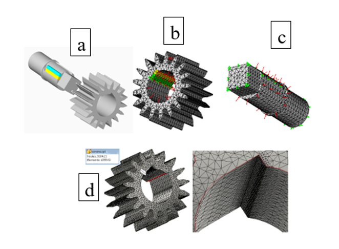
Figure 1 shows the digitization of this joint for finite element analysis; it is possible to observe the meshing and the application of loads and constraints made during the application of this method. As a mesh size, from a convergence analysis, an average size of 15 mm was applied for the elements, with a mesh refinement of an average size of 4 mm, applied in the key-crown (Figure 1d) and key-shaft contact zones, resulting in a total of 105 549 elements with 168 421 nodes for the crown.
These results are supported by a study by López-Ortiz et al. (2024), which details the considerations necessary to develop a reliable computational model that can be validated against specific criteria. That study uses Shell elements to study the impact on car bodies with a maximum size of 50 mm and a minimum of 16.62 mm, resulting in a total of 15 530 nodes and 23 403 elements. In comparison, their study uses larger elements, resulting in fewer nodes and elements.
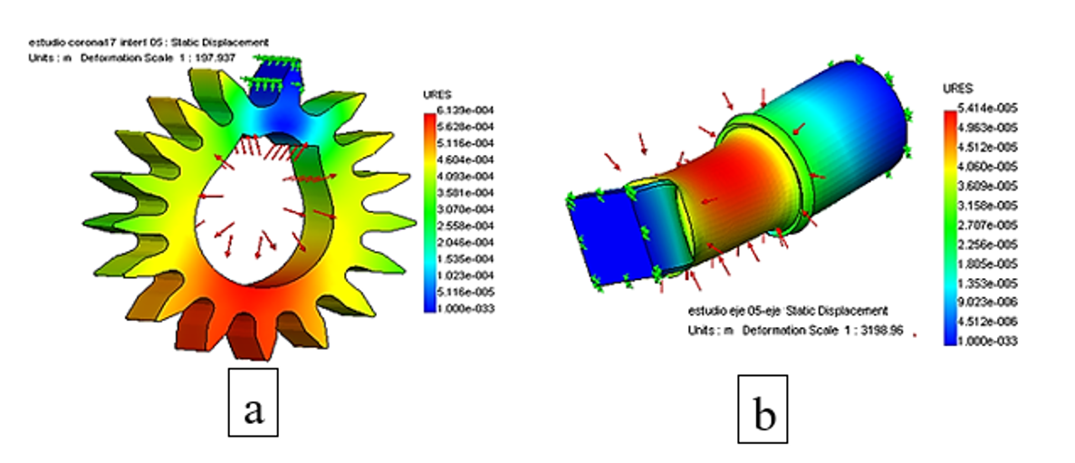
Part of the finite element analysis runs that enabled determination of the deformation corresponding to a given pressure level and vice versa is shown in Figure 2. In these types of mills, the aim is to reduce interference, and in this study, an interference fit of 0.5 mm is achieved at the height of the horizontal diameter of the crown, caused by a pressure p= 19.6 MPa.
According to studies by Moya et al. (2011), because the welded layer is harder, the teeth cannot flow, generating enormous loads on the mill and causing breakage of other elements. When the coating coefficient decreases to less than 1, high dynamic loads occur in the mill; therefore, a value greater than 1 must be achieved for all openings of the mill (Moya et al., 2011).
Figure 3 shows the result of the evaluation of the calculation of the interference resulting from programming the Lamé equation in Mathcad, on a simplified geometry of the joint, without considering the keyway recess or the cutting of the crown teeth.

Figure 3 shows a high coincidence between the two methods, with the analytical calculation yielding slightly higher pressure values caused by the same level of interference. For an interference of 0.5 mm, the analytical method yields a pressure of 20.2 MPa, which is 2.97% higher than that calculated by finite element analysis for the same interference (19.6 MPa).
The fundamental causes of sugarcane mill crown failures are several, but one of the main ones is interference between the flanks of the tooth (Moya et al., 2011).
Once the pressure caused by the interference (in this case, 0.5 mm) was calculated, it was possible to determine the circumferential frictional force (Ff) and the portion of torque () that can be transmitted by this route or by the friction pathway of the shaft-crown joint:
4). Where: A is the contact area between the crown and the shaft, m2; μ is the coefficient of friction between the shaft and the crown μ= 0.155; p is the pressure generated at the interference joint p= 19.6 MPa.
The contact area between the crown and the shaft was determined on the digitized drawings, using the ‘inspect-area’ tool of Autodesk Inventor, so as not to consider the recess in the area where the keyways are placed, resulting in A= 0.99 m2. Substituting the values of A, μ and p in expression 4 yields: N. The torque that can be transmitted with this frictional force will be given by: , where rc is the crown’s inner radius with a value of 0.285 m. Then, substituting in 5, the following is obtained: Nm.
The total torque that can be transmitted (Mt) is determined as a function of the motor power (Nm= 630 kW) and the rotational speed at the gearbox output (ω= 0.18 rad s):
It can be seen that the torque that can be transmitted by the friction caused by interference () represents 77% of the total torque to be transmitted (Mt). The study by Torres and Eras (2010) reports a torque of 7 162 Nm to be transmitted through the crown; the present study considers a torque 15 times greater, consistent with greater power and lower speed.
Torres assumes gear-only transmission; the present study shows that interference friction dominates transmission. The results of the present study suggest that mill crown models should incorporate the effect of friction/interference, as this may be the main mechanism, especially under low-speed, high-torque conditions.
The force applied to the crown gear tooth (), corresponding to the total torque (Mt), was determined as:
Where: rd is the distance from the center of the shaft to the contact area of the teeth during torque transmission (rd= 0.5053 m). Then, substituting in 7: N.
The force to be applied to the gear tooth to transmit the frictional torque is:
Subtracting this force from the total force, the resulting force (Fr) to be applied, which is to be transmitted by the keys, is determined:
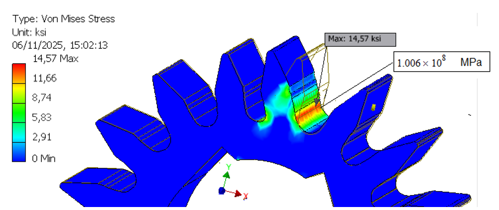
Figure 4 shows the stress distribution in the crown, determined by finite element analysis under the application of the loads calculated above. As can be seen, the maximum equivalent Von Mises stresses are located near the base of the crown tooth that transmits the torque, reaching a value of 100 MPa.
Figure 4. Comparing the maximum equivalent stresses in the contact zone of the keys with the crown to the yield strength of the crown material (320 MPa), the safety coefficient (equation 11) is obtained:
The safety coefficient obtained for the crown teeth (equation 12) is:
In this way, it is verified that, despite the reduction in the interference level, the crown failure would continue to occur in the tooth rather than at the contact area with the key. In studies where the change in the safety factor is analyzed under different conditions, its value increases from 0.959 in a simplified model to 3.48 in the journal; in the change of section, the safety factor decreases from 1.07 to 0.53. The variation in the magnitude of the torque consumed by the mill is determined based on its service factor, which is usually 1.2 (Murillo et al., 2004).
During the disassembly of the shaft-crown unit under study, corresponding to a tandem of mills of a sugarcane factory in the province of Mayabeque, Cuba, with the original interference level of the joint (Apo= 2 mm), a fuel volume of 120 L was consumed during the process of expansion by heating with a burner using diesel fuel.
Once subjected to a machining process with the new interference fit (Apo= 0.5 mm), the crown was assembled, consuming 65 L during its expansion and saving 55 L, representing a 45.8% diesel saving. Given that each mill has three shaft-crown joints, the fuel saving per mill, considering both assembly and disassembly processes, would be 165 L and for a tandem of six mills, the calculated saving would be 990 L.
During the monitoring of the operation of the joint subject to modification, no deficiencies were detected during the harvest period. As reported by Moya et al. (2011), the main causes of breakages in systems repaired by coating are due to increased hardness of the teeth; because the welded layer is harder, the teeth cannot flow and this generates enormous loads on the mill, causing breakages of other elements.
Determining the correct interference value (0.5 mm) ensures proper operation. It is not advisable to increase tooth rigidity unless uninterrupted contact of the teeth is guaranteed; in this study, it is possible to obtain the interference value that ensures continuous contact between the teeth.
The application of this method in the calculation of a transmission by tangential keys and a shaft-crown interference joint of sugarcane mills showed that, with an interference of 0.5 mm, it is possible to transmit 77% of the required torque through the key-crown joint, with a safety coefficient in relation to yielding greater than four and maintaining the base of the crown teeth as points most dangerous of the assembly.
The saving from the diesel invested during the assembly or disassembly of the modified crown was 45.8% of the fuel consumed at the original interference level of the assembly. During monitoring of the operation and technical condition of the modified assembly during the harvest and repair period, no deficiencies or effects attributable to the modifications made were detected.
Martínez, E. L.; González-Quiroga, A.; Jardini, A. L. and Maciel-Filho, R. 2009. Computational fluid dynamics simulation of the water-sugar cane bagasse suspension in pipe with internal static mixer. Jeżowski, J. and Thullie, J. (Editors). Computer Aided Chemical Engineering. Elsevier. 26(19):683-688. https://doi.org/10.1016/S1570-7946(09)70114-2.
Owen, D. R. J.; de Souza, N. E. A.; Zhao, S. Y.; Perić, D. and Loughran, J. G. 1998. Finite element simulation of the rolling and extrusion of multi-phase materials Application to the rolling of prepared sugar cane. Computer Methods in Applied Mechanics and Engineering. 151(3-4):479-495. https://doi.org/10.1016/S0045-7825(97)00173-4.
Quexel, H. B. 2004. Plan de mantenimiento para una máquina cosechadora de caña de azúcar marca Austoft 7700 y posibles causas que provocan las fallas más frecuentes en los motores diésel de las unidades de transporte del Ingenio Tululá SA. Tesis de ingeniería mecánica. Universidad de San Carlos de Guatemala, Facultad de Ingeniería, Escuela de Ingeniería Mecánica (USAC). Guatemala. 121 p.